Telephone: (+44) (0)843 289 9728
Email: kas at kaspencer dot com
choose one
for sale 2 - (scroll & read me)
AUTOMATIC LABELLING OF STOPS FOR
HAUPTWERK ORGANS - ITEMS FOR SALE
KASpencer offers
components for sale to those who wish to equip their
Hauptwerk organs with Automatic Electronic Stop Labelling.
The components which are not availablke anywhere elase are
offered as a Core Components Kit. With other, readily
available
components, and the accompanying Core Kit
Construction Manual, a cost-effective solution to the
labelling of stops with multiple Hautpwerk sample
sets is
overcome!
1.
THE CORE COMPONENT KIT
A Core Components Kit can be purchased from KASpencer, and
you source the rest of the items yourself. You would then assemble
the stop plate according
to the instructions in the
Electronic Labelling for Hauptwerk Organs Construction Manual.
The manual costs £17 + P&P and is available frome the link immediately
above.
When you have read the manual and are sure that
you can build the project, you may orderthe core kit of
components which are
described below.
Prices were correct
at the time of writing, but you are advised to check prices
before confirming your order.
1.1 Stop Plates
These are available
in quality beech ply, and black acrylic, which is a little more expensive.
One plate is required per stop jamb. They are of high quality, and professionally
cut by laser, and supports up to 70 stops per jamb.
Prices are:
Acrylic: £85 each; Beech Ply: £75 each, + P&P.
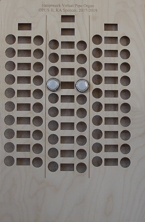
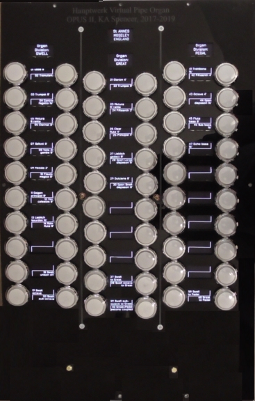
The plates have circular apertures for fitting the illuminated stop switches
(or solenoid drawstops), and rectangular for the display
of the OLED labels,
Scroll down to see the images of he two plates: on the left is shown the acrylic plate,
fitted with the OLED displays and illuminated stop switches.
On the right is shown the beech ply version, with just two illuminated stop switches in place.
(Scroll down for details of the printed circuit boards).
1.2
Printed Circuit Boards
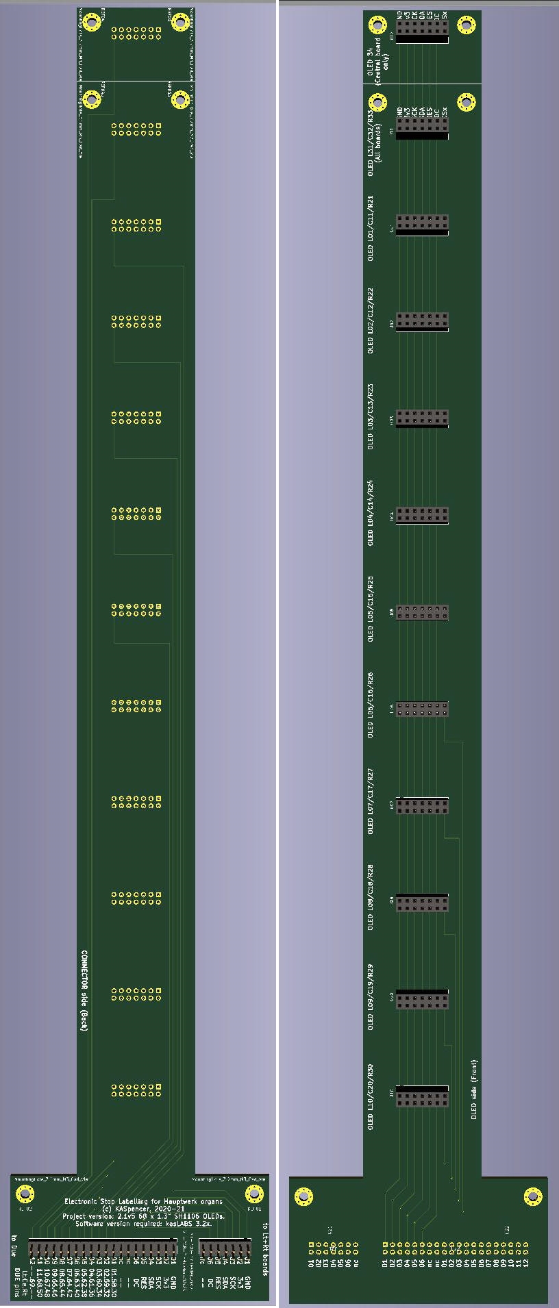
Three PCBs are required per stop jamb.
The Central PCB holds
12 displays, the lower 10 of which label 20 of the stops.
The top display can provide information about the organ currently loaded.
The second display can indicate the organ division whose stops
are labelled by the central PCB.
The Inner and outer PCBs
also label up to 20 stops on their lower 10 displays.
Their top displays can indicate the organ division whose
stops are labelled by the inner & outer
PCBs.
The PCBs are of high quality, and
professionally produced.
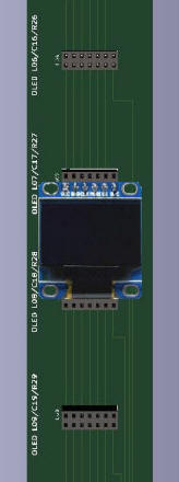
The image on the immediate right shows the Arduino Due
connector side, whilst that on the far
right shows the
OLED display side.
you will also need
to source and purchase:
- 60x 1.3" round
illuminated switches for 60 stops (20/40 reduce
accordingly);
- 240x spade connectors 120 red, 120
blue for 60 stops (20/40 reduce
accordingly);
- connectors for your chosen encoder & decoder (eg 10 x
40-way 0.1" SIL pin
strips);
- 1 x
64-port MIDI encoder (may be reduced to 32-port for a 20
stop build);
- 1 x 64-port MIDI decoder (may be
reduced to 32-port for a 20 stop build);
- 1 x 5v
PSU, 1 x 9-12v PSU, 1 x USB cable (micro-B to B-plug);
- a good supply of 0.05" 40-way ribbon cable and 3mm
heat shrink tubing.
Both images show PCBs with DIL
connector sockets fitted and soldered. Please note that PCBs
are NOT supplied with sockets, although they can be
fitted for an extra charge of £25 per PCB.
Prices are: £35 each, +
P&P.
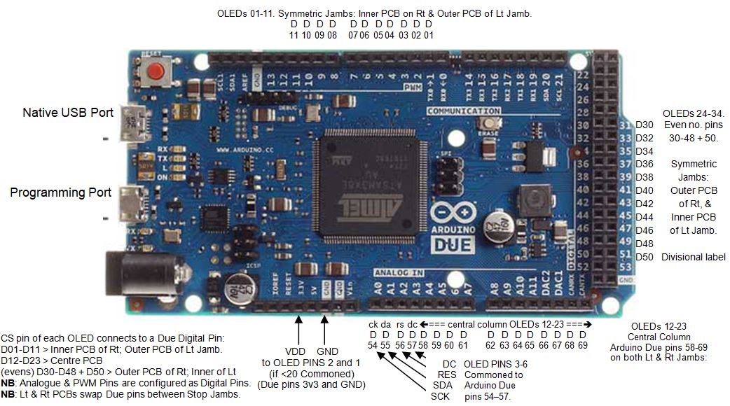
1.3 The Arduino
Due(s) and kasLABS software
The
labelling system is driven by an Arduino Due microcomputer,
under the control of purpose-designed software,
kasLABS v3.x. The Arduino connects to the
three PCBs via special cables, which you makeup as part pf
the project, using 40-way DIL IDC connectors and 40-way
ribbon cable. The cables are all illustrated and described
very clearly in the Core Kit Construction Manual.
The
image below illustrates the connections between the Arduino
Due and the three PCBs. Other pictures in the Core Kit
Construction Manual provide further clarification, as do
also the online YouTube videos.
You will need two Arduino Dues, each with the software
installed, if you build two stop jambs. You may also send in
your own Arduino
Due(s) and have the soiftare installed
for a small additional charge. The Dues are supplied with
USB Device Names to identify which Due should be in your
left jamb, and which in your right. Therefore, if you are
ordering only one Arduino Due, please indicate whether you
are building a left or a rignt jamb. This will ensure that
your stop label text is formatted and justified to best suit
the position of your stop
jamb(s).
Prices are:
per single
Arduino Due including kasLABs
software installed and tested £70 + P&P.
per
single
copy of kasLABS software
installed into your own Arduino Due and tested £35 +P&P.
(Please note: to have your own Arduino Due loaded with the
software, you must provide return postage included with your
P&P).
1.4 Other
Components
You must provide the other
components yoursef: they are all readily available online in
most countries. Some may be available from KASpencer but
lead times are unpredictable.
Full details of all
components are given in the Core Kit Construction Manual.
Building the PCBs
Here is a list of the other components required for each
PCB:
- 12 x 0.1" 2 x 7 DIL PCB sockets*, or 3 x40-way 0.1" SIL socket strips**;
- 1 x 0.1" 2 x 7 DIL PCB pin header, or
1 x 40-way 0.1" SIL pin strips;
- 1 x 0.1" 2 x 20 DIL PCB pin header,
or equivalent 0.1" SIL pin strips;
- 12 x 7-pin SPI SH1106 (1.3") OLEDs;
- 1 x DIL IDC 0.1" 2x7
ribbon cable header plugs***;
- 1 x DIL IDC 0.1" 2x20 ribbon
cable header plugs.
(*DIL=dual in line;
**SIL=single in line, ***IDC=insulation displacing connector)
- a
good supply of 0.05" 40-way ribbon cable and 3mm heat shrink
tubing.
The picture on the right shows an OLED
mounted into a socket on the PCB.
Adding the
Illuminated Stop Switches
If you do not already
have stop jambs with suitable illuminated stop switches (or
solenoid driven drawstops),
you will have to install 60 on
each stop plate.
For the
Illuminated Stop Switches, you will need to
source and purchase:
- 60x 1.3" round illuminated switches for 60 stops;
- 240x spade connectors 120 red, 120 blue for 60 stops;
- connectors for your chosen encoder & decoder (eg 10 x
40-way 0.1" SIL pin strips);
- 1 x 64-port MIDI encoder;
-
1 x 64-port MIDI decoder;
-
1 x 5v PSU, 1 x 9-12v PSU, 1 x USB cable (micro-B to
B-plug);
- a good supply of
0.05" 40-way ribbon cable and 3mm heat shrink tubing.
Each switch will have to be wired to an input of a
60-way MIDI Encoder: a suitable scheme is described in
detail, including connectors and ribbon cable between the
switches and the Encoder.
The LED in each switch body
must be wired to an output of a 60-way MIDI Decoder: s
suitable scheme is described for this too, along with
a
ribbon cable for the connections between each LED and the
Decoder.
The PSU will connect to the commoned +ve or -ve
terminals (according to whether you have a "Common +ve" or
"Common -ve" Decoder) of the LEDs, whilst their other
terminal connects to the Decoder outputs. The Core
Kit Component Manual will help with all that too.
The Core Kit Construction Manual explains
exactly how to do all of the above, and how to integrate the
switches with the PCBs.